These types of displays work in a clever way. Light passes through a polarising filter, through a liquid crystal, and then through a second polarising filter with the plane if polarisation orientated 90° to the first. The light then reflects off a mirror and follows the return path through the polarising filter, liquid crystal and polarising filter again.
In a liquid crystal, molecules can move about and flow, like in a liquid, but also be lined up in a structured way, like a crystal.
When there is an electric field across the liquid crystal, the molecules align. When there is no electric field, in pretty much all LCD screens since the 1990s, the molecules twist in a way that causes the plane of polarisation of light to rotate 90°. This way, when there is no electric field across the liquid crystal, the light passes through the first polarising filter, the plane of polarisation is rotated 90° by the liquid crystal, then the light passes through the second polarising filter with a plane of polarisation 90° to the first. Thus, light can be transmitted through the display whilst there is no electric field across the liquid crystal.
When there is an electric field across the liquid crystal, the molecules align so they have no effect on the plane of polarisation of light, and so the liquid crystal does not rotate the plane of polarisation of light. This means the light reaches the second polarising filter with a plane of polarisation 90° to the plane of polarisation of the filter, and no light is transmitted.
Two electrodes are placed on plates either side of the liquid crystal. One is a ground electrode covering the whole plate. The other electrode consists of different shaped parts which can be independently connected to a potential. These become the segments or dots of the LCD screen. Light has to be able to pass through these electrodes, so a transparent conductor alloy of indium, tin and oxygen (ITO) is chosen.
The complete display therefore has six parts.
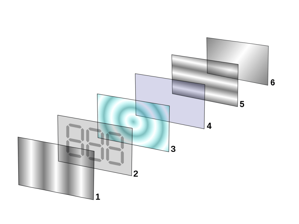
Part 1: the first plane polarising filter
Part 2: the glass plate with ITO electrodes arranged in segments or dots. Not pictured are the thin ITO connections from the segments to the edge of the glass plate, where wires can be attached to independently control the potential of each segment
Part 3: the liquid crystal layer
Part 4: the second electrode, ITO on a glass plate. The potential difference to create the electric field across the liquid crystal is between Part 2 and Part 4
Part 5: the crossed polarising filter, with the plane of polarisation 90° to Part 1
Part 6: the mirror or, in some displays, the diffuser. If this is a diffuser, there will be a light source behind it.
In colour LCD screens, there will be coloured filters over the different dot segments.
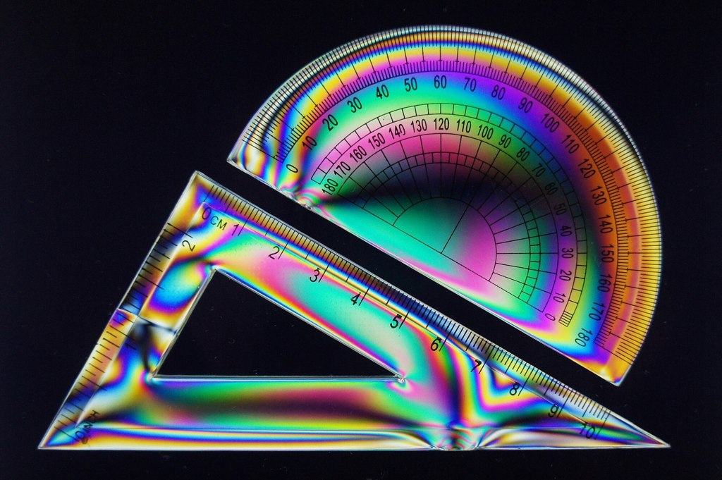
When I first saw how the polarisation plane of light can be rotated between two crossed polarising filters, and the beautiful effects it causes, I knew I had to study physics.
Reminder: Weekly Live Tuition Sessions!
SATURDAY 28th March 2026
| GCSE Physics | 9:30am | Transformers |
| A-Level Physics | 10:30am | Transformers |
| GCSE Astronomy | 11:30am | Stellar evolution (1) |
If you wish to enrol on the tuition sessions and haven’t yet, then click enrol below
