On the last day of the autumn term in 2023, an old colleague and dear friend of mine came to visit and donated a number of calculator relics and antiques to my collection.
As well as dropping off the antiques, he also wanted to show me how to use op amps for analogue computing and asked me to get some op amps out ready for when he got to school. This friend taught me so much when I worked with him, so I was more than happy to oblige!

One of the toys this friend dropped off was an old analogue computer (image 3), which made use of op amps to do arithmetic and, more excitingly, calculus. The equipment was electrically condemned for having no Earth protection, but I intend to fix that when I get back into the lab after the Christmas break; it’s easy to fix. Still, there’s no point having the analogue computer if I don’t understand how it works, and that was why my friend offered to teach me. It had been a long time since I’d used op amps. I hadn’t even thought about them since my electronics module at university during my physics degree. Back then, I drank a lot of alcohol and enjoyed many a night out at Jilly’s Rockworld (my favourite Manchester night club, may it rest in peace), and consequently my memory of much of my university education is patchy.
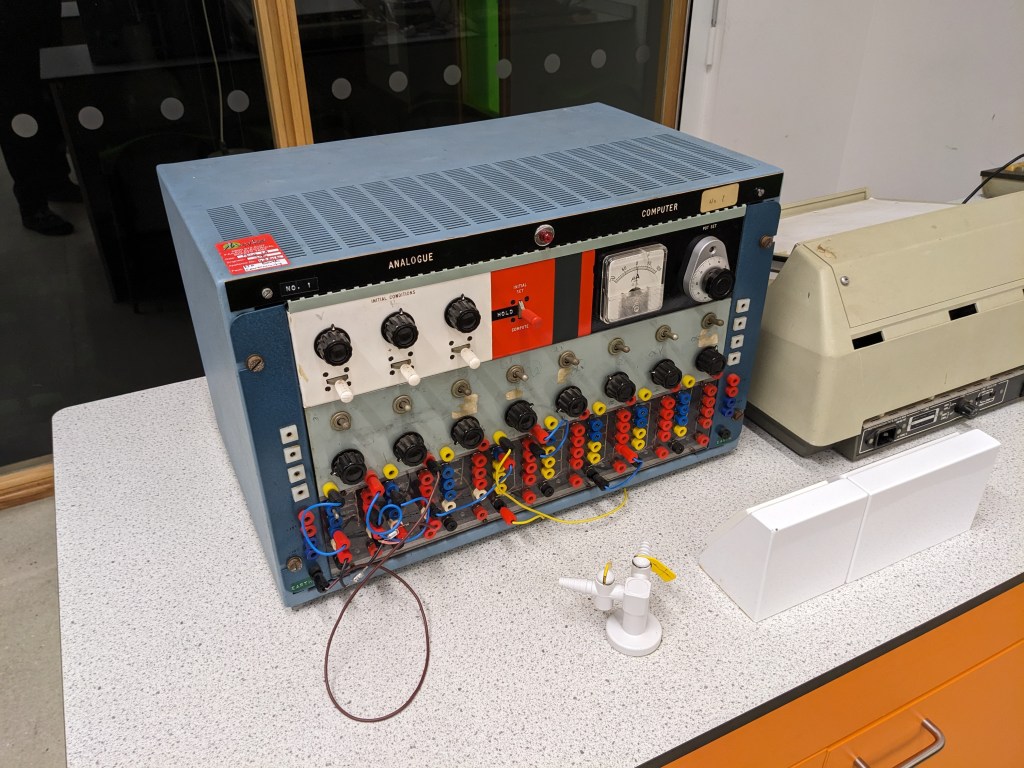
I will be recording a video about analogue computing when I’ve figured it all out. The teaching session finished with a crackling sound and a puff of blue smoke from one of the op amps; a sure sign that something had been connected wrong. Nevertheless, for a brief time, we did see the op amps differentiation a simple trig function.
Later I loaded up a circuits simulation program on my computer and started to fiddle around.

At first, I couldn’t make a lot of sense of how the op amp worked, but with the help of some other colleagues and friends, I got my head around it. In image 4, one can see the same potential applied to both inputs of the op amp, causing 0V output potential. That made sense. When connecting the inverting input pin to half the potential of the output (using two 10 kΩ fixed resistors as a potential divider), the output potential became 10V. Well, half of 10V is 5V, so that would make the inverting input potential 5V, the same as in the first case, yet the output potential is different. Actually, this is easy to reconcile (think, significant figures and rounding), but I’ll save that for the video.

Eventually, I got the op amp differentiating by using feedback. In image 5, the red trace shows the input potential and the blue trace shows the output potential, which is the first derivative of the input potential. I set the signal generator to produce three different functions; a sine wave, a square wave, and a triangular wave. The first derivative of each function is easily seen (well, -dF(t)/dt, not dF(t)/dt. The first derivative is inverted so I’d need to use a simple inverter op amp too, but this is just a proof of concept before I build the circuit for real)
I’ve not started planning or recording the analogue computing video yet, but it’s coming soon!
